Your cart is currently empty!
Paradox alarm system and Home Assistant with esp8266/ESP32 (without IP150)

If you want to integrate Paradox (most panels) alarm system to Home Assistant – you will need to pull/read data from the panel and feed it to MQTT (preferred) server. There are several options: IP150 module, serial (UART) or Serial-to-WIFI device, which I’m using now. The latter is cheap, small, easy to set up and should be robust solution. I was using IP150 previously – never again, it’s expensive, no meaningful integration etc. so I was happy when it was gone 🙂
You will need:
- esp8266/ESP32 module (any will work, even the bare ones if you know how to program them) or any device based on these like:
- NodeMCU, WeMos D1 etc. (the cheapest option): https://link.geriaune.pro/d1mini or
- the latest option (recommended for new installs)–there is a “super mini” ESP32-C3 version, which includes USB-C interface for programming, necessary outputs etc.: https://link.geriaune.pro/l5x43 or
- with a better wifi antenna: https://link.geriaune.pro/Nnv1Q
- Voltage regulator (to lower the panel’s +12V to 5 or 3.3V): https://link.geriaune.pro/dcdown
- 4 pin connector and connecting wires to put everything together: https://link.geriaune.pro/4pjst
I’m using ESP32-C3 SuperMini (mentioned above) from Aliexpress, nothing fancy. Same with voltage regulator. I’m converting +12V to 5V for my module–adjust to your needs. Most of these instructions are gathered from various sites and adapted to my specific situation:
https://github.com/ParadoxAlarmInterface/pai/wiki/Connection-methods#serial-over-ip-esp32
https://github.com/cybertza/PAI-ESP32
https://github.com/ParadoxAlarmInterface/pai/wiki
Connection diagram:

I’ve used regular TX/RX pins, also known as PIN21/PIN22 on my board. You can find other examples where logic level inverters are used, but in my case everything worked as expected without one.
I won’t be covering everything in this article, just all “gotchas” during install or configuration which I found very odd and strange as they were not highlighted anywhere else.
So starting from scratch:
- Install Home Assistant (I’m using Proxmox VE, so followed this guide – https://smarthomescene.com/guides/how-to-install-home-assistant-on-proxmox-the-easy-way/ )
- Install ESPHome Add-on
- Do a fresh (initial) install of ESPHome firmware on your board by adding a device in ESPHome add-on, select your board etc. etc.
and here’s the first catch – if your wifi is in the different subnet than your Home Assistant server – you will need to either specify a static IP address in the board config:
# Example configuration entry
wifi:
  ssid: MyHomeNetwork
  password: VerySafePassword

  # Optional manual IP
  manual_ip:
    static_ip: 192.168.0.123
    gateway: 192.168.0.1
    subnet: 255.255.255.0

    domain: .example.local
or add a correct DNS entry for new sensor named “paradox” in local DNS as mDNS for ESPHome will not work. I had this issue so I’ve just added a static DNS entry for “paradox.example.local” to my local pi-hole and that did the trick.
You might also want to adjust the default domain (to align with your existing one on the network) in the same “manual_ip” block as in the example above.
I’ve used ESPHome integrated serial-over-browser function “Plug into this computer” to upload firmware the first time and “Wirelessly” option every other time since then.
Once it reboots and connects to your network over WIFI – you need to:
- disconnect it from PC
- connect it properly to Paradox panel’s “SERIAL” header (4-pin, see connection diagram and links above)
- it should start and connect to WIFI again
- adjust config like this (standard things were omitted to not confuse different board owners):
# Enable logging
logger:
  # this is required if you use the same RX/TX pins as for logging
  baud_rate: 0

# this is for UART-to-IP conversion as you cannot tap into UART directly over network
external_components:
  - source: github://oxan/esphome-stream-server

# UART (serial) settings - pin21 and pin20 should be adjusted based on tx/rx port location on your board
uart:
  - id: paradox_uart
    tx_pin: 21
    rx_pin: 20
    baud_rate: 9600

# UART-to-IP server settings, this port will be used to connect from Home Assistant
stream_server:
  uart_id: paradox_uart
  port: 10000

# just a sensor to report if HA is connected to the board or not
binary_sensor:
  - platform: stream_server
    connected:
name: Connected- install new config to the board wirelessly from ESPHome
at this point you can telnet to the board using IP and port 10000, move around the house and if you see zones popping up in the terminal – all good and working. If not – check TX/RX connections on the panel, board, check config etc.
Moving on to Home Assistant and Paradox Alarm Interface add-on
- Install the PAI add-on like so: https://github.com/ParadoxAlarmInterface/pai/wiki/Home-Assistant
- Install MQTT server add-on. Or if you’re using external MQTT server (like I do) – install MQTT integration and specify your existing MQTT server/credentials there. Restart MQTT integration.
- go to add-ons and in PAI add-on switch to “configuration” at the top. Edit MQTT settings (based on your MQTT config) and set these config options:
# Connection Type
CONNECTION_TYPE: IP  		# Serial or IP

# IP Connection Details
IP_CONNECTION_HOST: '192.168.1.10' # Address of the ESP32
IP_CONNECTION_PORT: 10000             # Port of the ESP32
IP_CONNECTION_PASSWORD: 'paradox'  # IP Module password. "paradox" is factory default.
IP_CONNECTION_BARE: true           # Used this for base Serial over TCP tunnels
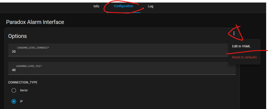
This is where the other “gotcha” is. Password for the panel is not required and “IP_CONNECTION_BARE” option is not in the GUI 😀 so leave the password as is (it cannot be erased so whatever…) and edit config as YAML:

and add “IP_CONNECTION_BARE: true” to the bottom. Save, restart PAI service. Without this option PAI will give you an auth error and will not function!
- go to Log, check for errors.
- No errors? Go to Settings->Integrations->MQTT and you should see/add new auto-discovered alarm panel device.
- Inside this device all panel options/zones/partitions should be visible:

You’re all set!!! Get a beer and add Alarm blocks to the dashboard if you so desire 🙂
Several things to note:
- Panel will take only one connection at a time, so if your esp board, telnet session, PAI etc. etc. got hung – PAI add-on will not re-connect to the panel until it’s cleared. So a hard reboot (disconnecting power and battery) of the panel and the esp board will solve this.
- There can be only one – meaning IP150/RS232/ESP etc. – pick one. No simultaneous connections to UART for these panels are possible. At least in my experience.
I will be posting more uncensored or exclusive content on Patreon:
https://www.patreon.com/geriaune
If you want to drop me a beer: https://paypal.me/geriaune
